Network management should be faster & easier.
Read the June 2022 Network Visibility Capabilities Report by Tolly to learn how Auvik delivers industry leading time to value.

What you’ll get in this report
About this report
Time to Read: 14 min | Audience: IT decision makers | Last Updated: July 2022
Auvik commissioned The Tolly Group to prepare this independent report (#222131). Tolly is a leading global provider of third-party validation services for vendors of IT products, components, and services.
Executive Summary
Solving user connectivity problems requires visibility into those problems. It is essential that all locations, networks, and devices be quickly visible and easily navigated to expedite the problem-resolution process. Auvik has designed its cloud-based network monitoring and management solution to allow friction-free, rapid access to all network devices.
Auvik commissioned Tolly to evaluate its network visibility system versus the network visibility capabilities of three other prominent solutions. These solutions represented both commercial options licensed by node and by sensor and open source options. These will be referenced generically. Tolly evaluated installation and functional capabilities such as dynamically generating topology maps, providing network visibility by IP subnetwork and VLAN, and providing detailed information about network infrastructure devices and access to those devices.
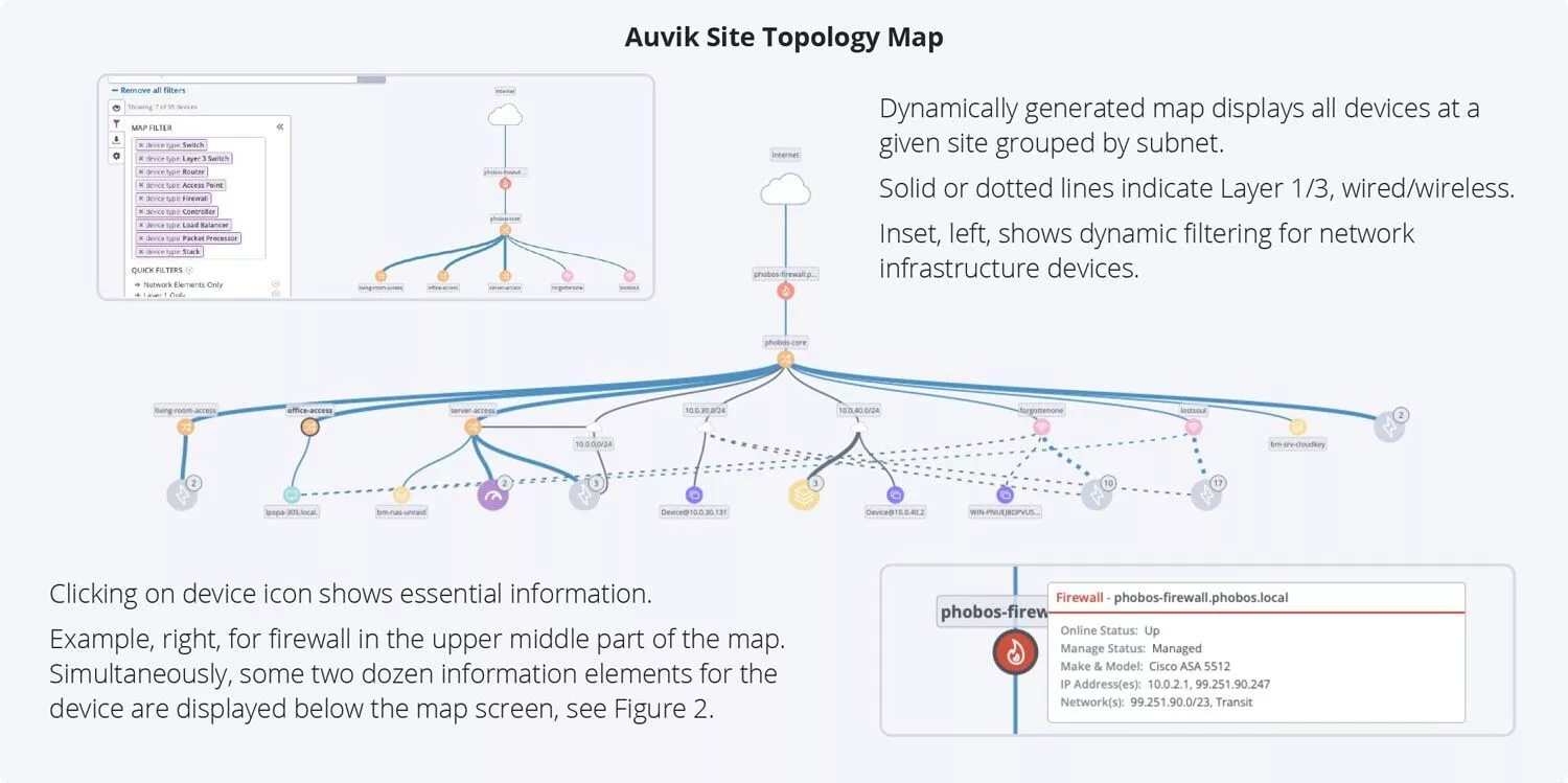
Auvik was very easy to install and configure for discovery. Auvik generated a topology map dynamically and provided network inventory by subnet and details on network infrastructure. Auvik’s capabilities exceeded those of the other solutions. See Figure 1 for the topology map.

Tolly structured the evaluation to follow a workflow natural for many network admins. First, came the installation and deployment steps. As that is a one-time 1 process, that will be described later.
Once installed, Tolly believes that most admins will proceed with a “top-down” approach. That is, start at the highest level of visibility and progressively navigate down to the subnet and devices of interest. See the Test Setup & Methodology section for more details.
The Bottom Line. Auvik Delivers.
Too busy to read the full report now? Download it for when you have more time.
With Auvik, the user can view a complete environment map generated automatically by the Auvik solution.
Test Results
Dynamic Topology Mapping
With Auvik, when the discovery process is complete, the user can view a complete environment map generated automatically by the Auvik solution. See, again, Figure 1.
This hierarchical map organizes the site by subnetwork and provides links that clearly show devices that have interfaces connected to more than one subnet.
Not only is the map generated dynamically (i.e., without any user intervention), the map itself is dynamic. This is, understandably, difficult to show in a static image. To help illustrate some of the dynamic features, there are several overlays on Figure 1.
The overlay on the upper left shows some of the filters that can be applied dynamically to the topology map to help the network admin focus on specific devices or device types of interest. The associated network diagram shows fewer nodes as those not currently of interest have been temporarily filtered out.
The overlay on the bottom right illustrates the summary device information that is displayed when the cursor hovers over a device, in this case, the Cisco firewall. (Auvik collects much more information about the firewall. That will be discussed presently.)
See Table 1 for a summary of all test results.

Not one of the other solutions provided a comparable, dynamically-generated topology map.
The OS solution showed nothing, only its own management server. The PN solution’s “map” was just a device list in visual format. There was no hierarchical organization that mapped to subnets. The PS solution did not provide any overall map. Testers did find that if one navigates to a given switch, that switch will present a diagram showing all of the network infrastructure devices connected to it but did not display any endpoint devices at all.
Some of the solutions note that topology maps can be built manually but that did not fit the requirements of the current test as the test was focused on time savings.
Devices by Subnet
The next area of interest to a network admin would likely be to drill down and look at all devices and infrastructure in a logical group. For networks today, that would mean grouping devices by IP subnet and VLAN group. In all cases, these would likely be the most important groupings of devices for network admins.
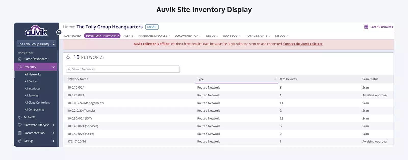
Auvik provides this hierarchical listing of subnets through its “Inventory” screen which is a single click away at all times. It lists the groupings, notes whether the group is a routed network or a VLAN, provides a device count, and a scan status. See Figure 2 below.


None of the other solutions offered any similar capabilities. In fact, some of the screens labeled “Device List” by the other solutions were nothing more than interface lists. That is, what was labeled as “devices” simply listed all the interfaces that the solution detected in the network. In most cases, multi-interface devices (e.g. routers, access points (APs)) were not identified as being a single, multi-interface device. None of the other solutions provided, by default, organization or segmentation by subnetwork or VLAN.
While one or more solutions might allow this type of organization to be built manually, this did not fit the requirements of the current test.
Network Infrastructure Device Details
Finally, the admin would want to look at details for a specific network infrastructure device. For this part of the test, engineers evaluated how each solution reported key device attributes for several major brand switches, a firewall, and a popular access point.
The information queried included serial number, software version, and various interface and utilization metrics. Additionally, testers determined whether a configuration backup could be made via the solution. Additionally, for the AP, testers determined whether the solution could report a list of end devices associated to this AP.
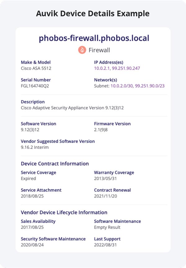
Auvik reported all this information accurately, was able to execute a backup of the running configuration, and listed all 2 devices connected to the AP. Figure 3 shows a graphical depiction of the Auvik device details for the firewall. (Not all information collected is shown in that figure.)
Expand for Device Information Detailed Results

The results from the other solutions varied considerably.
The PS solution had the best results of the competitors, though still incomplete compared to Auvik. It was able to report all of the device attributes except for reporting broadcast traffic. Also, it was able to run a backup on the configuration file. Interestingly, this solution failed with respect to the WLAN AP. It did not recognize it as a network infrastructure device and, thus, provided no information at all about it.
The PN solution provided some, but even less, information. It was able to collect the serial number and software version from some of the network infrastructure devices but, for others, reported an error and displayed no results. Troubleshooting errors was beyond the scope of the current test.
As with the PS solution, the PN solution did not report broadcast traffic. Generally, it also failed to report CPU and memory utilization. This solution was not able to run backups of device configurations. As with the prior solution, the PN solution did not recognize the AP (Ubiquiti) as a network device. Rather, it was identified as a Linux server. Because the solution did not detect that it was a network infrastructure device, it did not report any information about it or any list of connected devices.
Installation & Deployment
The Auvik installation was, as advertised, very quick. After downloading the installer (three minutes), the installation was completed in under six minutes. At that point, Auvik was ready to discover the networks and begin report. As with all solutions, device credentials would be entered as part of the discovery configuration. Auvik implements a hierarchical credentials system which can dramatically decrease the time spent inputting credentials.
The PN solution installed in 12 minutes but requires individual credentials per device which can add significantly to the overall deployment time.
The PS solution required 53 minutes to install but also required individual credentials.
Common Sense TCO/ROI
You don’t always need a calculator to demonstrate TCO/ROI. Auvik’s well-designed, intuitive GUI allows network admins to just “jump in” and use Auvik to monitor and manage their network. Tolly found Auvik could be used without training and had basically no learning curve. With Auvik’s ease and rich functionality, TCO/ROI are improved by reducing effort on the part of the admin and by the admins solving problems more quickly.
Auvik in a Nutshell
See Auvik in action, on your network
Deploy Auvik in under 30 minutes and monitor as many devices as you like in this 14-day free trial.
Test Setup & Methodology
Approach
Tolly designed the test process to follow the approach that could be taken by a prospective customer conducting its own “proof of concept” (PoC) trial of each of the four solutions. Thus, it was assumed that person conducting the trial would be an experienced network engineer who understood general installation concepts but did not have prior experience with either installing any of the solutions under test. Testers followed all instructions provided by the vendor from the initial download demo link. In some instances, there were multiple installation options. For example, a solution might offer components as a Windows installer or as a virtual appliance with a preinstalled system. Testers chose what appeared to be the most efficient installation path. Understanding that PoC teams cannot afford to spend unlimited amounts of time, Tolly placed a limit of 10 man-hours on installing and configuring (deploying) a system before running its evaluation. (Not all solutions required anywhere near this amount of time.) The goal was to deploy the system using the guidance each solution provided within the installer. When this was not sufficient, public documentation and vendor knowledge bases were searched. In at least one case, at the end of available deployment time, some features were either not found or not working. The PoC review was conducted with what functionality could be found or be made working within the prescribed time window and reported accordingly.
Test Environment
The environment consisted of six LANs, each its own IP subnetwork, linked together by a core switch that provided a link into a Cisco firewall and from there to the internet. A total of 50 unique devices were connected across the LANs. These included switches, routers, access points, servers, and user devices both desktop and mobile. The unique infrastructure devices consisted of a Cisco ASA firewall, an HPE ProCurve switch, Cisco SG 300 switch, an HP Comware switch, and a Ubiquiti AP.
Test Methodology
In keeping with the PoC approach, the test methodology was kept simple and straight forward. While the network contained dozens of user devices, the focus was on the network infrastructure devices.
Installation & Deployment
Testers downloaded any required modules and followed each solutions installation instructions. Once installation was complete, testers followed the instructions required to provide whatever information was needed for the solution to begin the discovery process.
Topology Mapping
Testers started at the main screen of each solution and determined if the system had built a topology map dynamically. If no map was found, documentation was searched to determine the solution’s capabilities.
Subnet Display
Testers used the solution GUI and attempted to find a menu option that would display all discovered devices organized by a given subnet.
Device Details
Testers navigated into the detailed information for the aforementioned infrastructure devices and determined which device details were accurately reported by each solution.
